When metallurgical
engineers discuss the history of failure analysis and the analysis
of the surface of a failed sample (known as fractography), the discussion
is usually divided into two time periods: before the development
of the scanning electron microscope (SEM) and after. This sums up
the importance of the SEM in determining the cause of failures through
the examination of the microscopic features present on the fracture
surfaces which were created while the material was failing. When metallurgical
engineers discuss the history of failure analysis and the analysis
of the surface of a failed sample (known as fractography), the discussion
is usually divided into two time periods: before the development
of the scanning electron microscope (SEM) and after. This sums up
the importance of the SEM in determining the cause of failures through
the examination of the microscopic features present on the fracture
surfaces which were created while the material was failing.
The SEM has
several important characteristics that make it the optimum instrument
for fractography. First, the SEM is capable of very high magnifications,
able to magnify features from 10 to 100,000 times. This is critical
because many of the microscopic features cannot be resolved at magnifications
much below several thousand times. For comparison, most optical
microscopes are limited to a maximum magnification of 1000 times.
Secondly, the SEM has tremendous depth of field. The field of focus
on a SEM is several hundred times greater than that of an optical
microscope, and approaches that of the human eye. Anyone who has
used an optical microscope in a science classroom can remember how
difficult they are to focus. One can either focus on the high spots
or the low spots, but never on both. The SEM can keep the high and
low spots in focus, which is critical because even the smoothest
fracture truly is a mountain range of high peaks and low valleys
when viewed at high magnifications.
Once viewed
on the SEM, each fracture reveals its own characteristic pattern
of microscopic features that are easily photographically documented.
But what do all these features represent? What do they tell you
about why the component failed?
Each failure
mode or type of failure has a characteristic set of fractographic
features. While some of the details of each may differ depending
on the exact material that failed, or the exact conditions of the
failure, the features are very similar in most circumstances. This
allows the experienced metallurgical engineer to determine the fracture
mode with SEM examination. Since some fractures may show different
features in different areas, the experience of the engineer is critical
in determining the direction and sequence of these features to understand
the cause of failure.
Ductile Dimples: uniform from tension
(left), elongated from shear (right).
1000X1000X
DIMPLES are
indicative of a ductile overload failure. They look like craters
on the moon, as seen in the photograph. Dimples indicate the loads
applied to cause the failure of the component are in excess of the
tensile strength of the material, and that the material has ductility,
or the ability to deform. When dimple features are present and ductile
overload has occurred, the component typically shows macroscopic
signs of deformation, such as bending, necking down, or stretching.
Visually, the surface is generally not flat, and may have several
layers or deep valleys on the fracture surface. The metal microscopically
pulls and stretches, creating microscopic voids. The voids then
further stretch until they break in half. Each dimple is half of
a microscopic void. Uniform equiaxed voids indicate the loading
is in tension, while elongated or stretched voids indicate shear
or bending load. This failure mode is often referred to as microvoid
coalescence.
INTERGRANULAR
features indicate the fracture has progressed through the grain
boundaries in the material, and not through the grains. They give
a very distinctive "rock candy" appearance as seen in
the photograph. Optically, the fracture may have a sparkly appearance,
as each of the smooth grains easily reflects light. Macroscopically,
the components generally will not show deformation or stretching,
since intergranular fractures typically are a brittle failure mode.
While some materials will fail intergranularly as a matter of course,
these are generally pure metals. Most materials fail intergranularly
because a weak phase is present along the grain boundaries, making
the grain boundaries weaker than the grains and thus the easiest
crack path. The hardened case in a carburized steel generally has
fine carbides along the grain boundaries, creating an intergranular
failure in the case, with a ductile dimpled fracture in the core.
Likewise, some tool steels or exotic materials with grain boundary
phases will fail intergranularly. Stress corrosion cracking, a time
dependent failure mode which requires the presence of a corrosive
environment and an applied or residual stress, can run intergranularly
in some materials and some environments. But perhaps the most common
and most worrisome intergranular failure mode is hydrogen embrittlement.
Hydrogen typically from a plating or cleaning operation is absorbed
into the metal and congregates along the grain boundaries, creating
an intergranular failure mode in a material which would be expected
to fail in a ductile manner at much higher stress levels.
Intergranular (left): with features similar
to rock candy. Cleavage (right): with fan-like features.
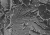
300X 1200X
CLEAVAGE fracture
is a transgranular failure mode where neither dimples nor grain
boundaries are evident. Cleavage features are flat and fanlike,
as seen in the photograph. Similar to intergranular fracture, it
is a brittle failure mode, and thus no macroscopic signs of deformation
or stretching are typically present on the component. Like ductile
overload, it is an overload failure mode indicating the stresses
applied to the component exceed the tensile strength of the material.
Materials with low fracture toughness exhibit brittle cleavage fracture.
These include steels that fail at temperatures below the ductile
to brittle transition temperature, and those experiencing temper
embrittlement. Cleavage cracking progresses through the material
very rapidly, often creating a rapid, unforgiving and often dangerous
failure.
Fatigue: with fine parallel lines called
striations.
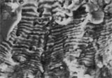
2000X
FATIGUE fracture
is caused when stresses lower than the tensile strength of the material
are applied cyclically. Cyclic loading can be vibrational, rotational,
bending or similar, and can occur over 100 cycles, or 10,000,000
cycles. The key element is cyclic loading. After an incubation time
for the microscopic strain to build up locally in the component,
the crack initiates, and propagates by tearing a very small distance
during each cycle of loading. Each tear is called a striation, and
the cracking creates a pattern of fine lines across the fracture
surface as seen in the photograph. This is a very unique pattern.
The striations are generally more easily distinguished on ductile
materials, such as stainless steel or aluminum, and less readily
noticeable on high strength or low toughness materials. Unfortunately,
with each cycle of loading, the fractures often rub together and
damage the striations replacing them with wear and smearing. Macroscopically,
fatigue failures tend to be very planar, with no deformation present,
and typically start at a notch, corner or defect. After each loading
cycle, the fatigue crack grows and reduces the usable cross section
of the material. After a time, the remaining cross section of material
can no longer support the applied loads and the fracture completes
itself in a single overload event. That is why ductile overload
dimples are often also found at some locations on a fracture surface
of a component failing by fatigue.
SEM Fractography
is another tool that we at MEI utilize to determine the cause of
fracture and thus gain an understanding of the failure scenario
and all the related causative factors. Only when all these have
been identified can the proper corrective actions be implemented,
so that future failures can be prevented.
Materials Engineering
recently achieved accreditation by the American Association for
Laboratory Accreditation (A2LA). This organization is a nonprofit
organization that is the recognized leader for accreditation of
testing laboratories. A2LA has audited our quality system to ISO/IEC
Guide 25 "General Requirements for Accreditation of Testing
Laboratories". This specification is the generally recognized
standard for testing laboratories, and includes the principles of
ISO 9000 but also contains tougher requirements for qualification
and competence of testing personnel and procedures, insuring that
a laboratory has the technical abilities to conduct testing, and
not just having the proper paperwork in order.
Accreditation
can be thought of as formal independent recognition that a laboratory
is competent to carry out specific tests using recognized test procedures,
trained personnel and calibrated equipment.
As part of the
accreditation process, we successfully completed an audit by A2LA's
team of independent auditors, and will continue to be audited biannually.
The scope of the audit includes a complete review of the quality
system, test procedures, policies, training, equipment calibration
and manuals. The auditor also watches over the shoulders of our
staff as we conduct testing to insure our competence to perform
testing. These audits provide opportunities for continual assessment
of ourselves, allowing us to maintain the high quality of our laboratory
services.
A2LA accreditation to ISO Guide 25 insures:
• Testing is conducted in compliance to nationally recognized
test procedures, including ASTM and SAE test specifications.
• Internal procedures are in place to insure continued proper
calibration of test equipment using NIST traceable standards.
• All testing is performed by trained, knowledgeable skilled
professionals, who follow the clearly defined test procedures.
• Internal audits are conducted to insure procedures and policies
are being followed.
• Any testing subcontracted by MEi will be conducted only
by companies who have a similar commitment to quality.
• Reports and technical records will be maintained in such
a manner to allow verification of test results and traceability
well into the future.
In addition to
the accreditation, Materials Engineering, Inc., participates in
collaborative testing programs. In these programs, identical samples
are tested by laboratories across the country, with the results
statistically analyzed. This insures our test methods yield results
similar to other testing laboratories.
Our desire is
that through our accreditation and participation in collaborative
testing program, you and your customers to have full confidence
in the testing and analysis you entrust us to conduct.
We will be happy
to provide a copy of our scope of accreditation to customers whom
require such documentation as part of their quality system requirements.
The scope of accreditation includes failure analysis, SEM/EDS, hardness
and microhardness, metallography and microstructural evaluation.
For more information
on ISO Guide 25, contact A2LA at 301-670-1377.
MEi President
and Principal Engineer, Bill Durako, addressed the Rockford Chapter
of ASM International during their January Dinner Meeting. ASM International
is the largest technical society dedicated to Materials and Metallurgical
Engineering. Bill's presentation was titled "Case Studies in
Failure Analysis" and presented some of the more unusual and
interesting projects he has worked on through the years. The case
studies came from legal, insurance and industrial failures, and
covered items including golf clubs, bicycles, arson investigation,
gas line explosions, automotive dashboards, construction equipment,
washing machine hoses and food packaging products.
Perhaps the
most interesting involves a design related case where the inadvertent
changes in geometry and material thickness on a pull tab food can
caused the can to "explode" when opened. The hands on
demonstration startled the audience when they heard the loud noise
produced when that can was improperly opened.
The presentation
was meant to be as entertaining as educational. If you would like
one of our engineers to speak at your company or technical society,
please give us a call. If you are interested in ASM international,
their national headquarters and membership information are 1-800-336-5152
or www.asm-intl.org.
The scanning
electron microscope (SEM) is a powerful tool, capable of magnifications
up to 180,000 times. It allows us to reveal information which is
critical to metallurgical investigations, such as fracture modes
and surface characteristics.
The SEM can also
be fun to play with, because it allows one to view the surface of
anything at high magnification with great depth of field. All of
us have been amazed by the pictures of various insect parts, especially
the eye of a fly.
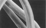
In our contest,
we take a look at an object on the SEM that should be familiar to
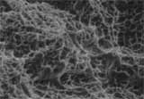
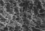
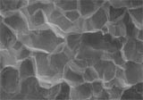
all of you. In this issue's contest, we have three different fabrics
which we ask you to identify. Please note the differences in magnification
on the photographs, as one is much smaller than the other two. As
there are three photographs, we thought it only fair to give you
some help. Not necessarily in order, the three fabrics are A) famous
for sweaters B) from the orient C) the "fabric of our lives"
Can you identify all three?
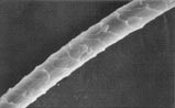 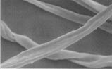 
600X 600X
1200X
Please fax, mail
or e-mail us (don't call) with your answer. We will draw a winner
from all correct entries received by June 6. The correct answer
and the winner will be published in the next issue Of Materials
Interest.
The prize is
a $50 restaurant gift certificate, so put on your thinking caps.
Results:
Last issue, we
showed photographs of a natural substance from our 50th state. Many
of you correctly identified the substance as lava, or lava rock.
We were fascinated by the needle-like structure formed upon solidification.
Our winner, drawn at random from the correct entries, was Mark Hlinak,
Analytic Chemist from CR Industries in Elgin, Illinois. Mark received
a gift certificate for dinner at Bob Chinn's Crabhouse in Wheeling.
CR Industries, once known as Chicago Rawhide, is the world's leading
supplier of fluid sealing devices for the truck, automotive, farm
equipment, aircraft, heavy machinery and machine tool industries.
CR also supplies seals for aerospace missiles, earth moving equipment,
appliances and a wide variety of pumps, hydraulic systems, motors
and subassemblies. Congratulations, Mark!
|